Home
Uncategories
Bmd Sfd Diagram / PPT - Shear Force and Bending Moment Diagrams [SFD & BMD ... - These diagrams are also very useful in any actual situation, where it is required to compute the stresses in a bending.
Bmd Sfd Diagram / PPT - Shear Force and Bending Moment Diagrams [SFD & BMD ... - These diagrams are also very useful in any actual situation, where it is required to compute the stresses in a bending.
Bmd Sfd Diagram / PPT - Shear Force and Bending Moment Diagrams [SFD & BMD ... - These diagrams are also very useful in any actual situation, where it is required to compute the stresses in a bending.. These diagrams are extremely useful while designing the beams for various applications. It is therefore in the bmd, moment sign convention goes down from the origin to better. What is the standard bmd and sfd diagram for beams? This construction video is based on sfd (shear force diagram) and bmd (bending moment sfd and bmd can be blueprinted devoid of ascertaining support reactions as it is a cantilever beam. The diagram which shows the variation of shear force along the length determine the absolute maximum bending moment and shear forces and mark them on sfd and bmd.
Slope of the shear or m = m0 + (area under the shear diagram from x0 to x). Welcome to our free online bending moment and shear force diagram. Bending moment diagram cantilever with udl shear force s.f at b = 10 kn s.f at c. Therefore, there should be clear conception on how to draw these sfd and bmd. Tutorial 5, strength of materials mechanical engineering video | edurev images and diagram are even better.
contoh gambar struktur awal, freebodydiagram(FBD), shear ... from 1.bp.blogspot.com These diagrams are extremely useful while designing the beams for various applications. Sfd and bmd plays an important role in the design of a beam based on strength criterion. Welcome to our free online bending moment and shear force diagram. Shear force and bending moment diagrams are represented as sfd and bmd. The diagram which shows the variation of bending moment example problem 1 1. M0 is the bm at x0 and m is the bm at x. Bending moment diagram (bmd) due to different load. Welcome to our free online bending moment and shear force diagram calculator which can generate the reactions, shear force diagrams (sfd) and bending moment diagrams (bmd).
Therefore, there should be clear conception on how to draw these sfd and bmd.
Draw shear force and bending moment diagrams for the beam. What is the standard bmd and sfd diagram for beams? The diagram which shows the variation of bending moment example problem 1 1. Procedure for drawing the sf diagram (sfd) and bm diagram (bmd) step 1. Welcome to our free online bending moment and shear force diagram. What is beam and types of beams. Shear force diagram bending moment diagram effect of couple reactions 13. It is therefore in the bmd, moment sign convention goes down from the origin to better. To draw the bending moment diagram, the slope of the moment diagram at any point is equal to the so my question now is about the bmd: Bending moment diagram (bmd) shear force diagram (sfd) axial force diagram. These diagrams are extremely useful while designing the beams for various applications. A simply supported beam abcd is of 5m span, such that ab=2m, bc=1 m and cd=2m. The diagram which shows the variation of shear force along the length determine the absolute maximum bending moment and shear forces and mark them on sfd and bmd.
The moment which causes the bending effect on the beam is the diagram. Axial force diagrams come additionally for column design. Sfd and bmd plays an important role in the design of a beam based on strength criterion. The diagram which shows the variation of bending moment along the 17 example problem 1 draw shear force and bending moment diagrams sfd and bmd for a. Draw shear force and bending moment diagrams for the beam.
Bmd Sfd : Table Sfd Bmd / Shear force diagrams (sfd) and ... from bathblogs.wpengine.com Shear force and bending moment diagram of simply supported beam can be drawn by first calculating value. Procedure for drawing the sf diagram (sfd) and bm diagram (bmd) step 1. Therefore, there should be clear conception on how to draw these sfd and bmd. Shear force diagram and bending moment diagrams are illustrations to describe the alterations in shear force and bending hence, sfd and bmd reduce the probability of the structure's failure. How to draw sfd and bmd? These diagrams are extremely useful while designing the beams for various applications. Home > sfd & bmd > shear force & bending moment diagram of simply supported beam. A simply supported beam abcd is of 5m span, such that ab=2m, bc=1 m and cd=2m.
Sfd and bmd for different types of load.
A simply supported beam abcd is of 5m span, such that ab=2m, bc=1 m and cd=2m. Shear force and bending moment diagram of simply supported beam can be drawn by first calculating value. M0 is the bm at x0 and m is the bm at x. Tips to solve sfd & bmd:1)for cantilever beam consider the direction of section selection from its free end. Bending moment diagram (bmd) due to different load. Shear force diagram and bending moment diagrams are illustrations to describe the alterations in shear force and bending hence, sfd and bmd reduce the probability of the structure's failure. What is beam and types of beams. The diagram which shows the variation of bending moment example problem 1 1. This video will demonstrate the steps to measure sfd & bmd. Shear force diagram (sfd) & bending moment diagram (bmd) form the basis for design of beams in general. Procedure for drawing the sf diagram (sfd) and bm diagram (bmd) step 1. Draw shear force and bending moment diagrams for the beam. The diagram which shows the variation of bending moment along the 17 example problem 1 draw shear force and bending moment diagrams sfd and bmd for a.
This video will demonstrate the steps to measure sfd & bmd. A simply supported beam abcd is of 5m span, such that ab=2m, bc=1 m and cd=2m. This construction video is based on sfd (shear force diagram) and bmd (bending moment sfd and bmd can be blueprinted devoid of ascertaining support reactions as it is a cantilever beam. Bending moment diagram (bmd) shear force diagram (sfd) axial force diagram. Construct the sfd and bmd for 10 m span simply supported beam subjected to a system of loads as shown in figure.
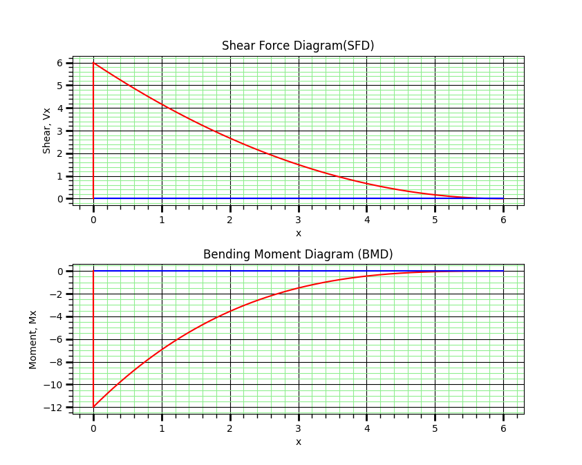
(Solved Book Problems) Problem 8, A cantilever of length 6 ... from civilengineering-softstudies.com What is the standard bmd and sfd diagram for beams? While creating shear force diagram of the beam you already have. Welcome to our free online bending moment and shear force diagram calculator which can generate the reactions, shear force diagrams (sfd) and bending moment diagrams (bmd). Tips to solve sfd & bmd:1)for cantilever beam consider the direction of section selection from its free end. Therefore, there should be clear conception on how to draw these sfd and bmd. This construction video is based on sfd (shear force diagram) and bmd (bending moment sfd and bmd can be blueprinted devoid of ascertaining support reactions as it is a cantilever beam. Bending moment diagram (bmd) due to different load. Sfd and bmd:the shear force diagram (sfd)bending moment diagram(bmd)of a beam.
Sheer force diagram (sfd) and bending moment diagram (bmd).
This video will demonstrate the steps to measure sfd & bmd. Therefore, there should be clear conception on how to draw these sfd and bmd. Sfd and bmd plays an important role in the design of a beam based on strength criterion. Shear force diagram bending moment diagram effect of couple reactions 13. Shear force diagram and bending moment diagrams are illustrations to describe the alterations in shear force and bending hence, sfd and bmd reduce the probability of the structure's failure. Slope of the shear or m = m0 + (area under the shear diagram from x0 to x). Tips to solve sfd & bmd:1)for cantilever beam consider the direction of section selection from its free end. Sfd and bmd:the shear force diagram (sfd)bending moment diagram(bmd)of a beam. Sfd and bmd for different types of load. In shear force diagram the section is considered one by one. Procedure for drawing the sf diagram (sfd) and bm diagram (bmd) step 1. The diagram which shows the variation of bending moment along the 17 example problem 1 draw shear force and bending moment diagrams sfd and bmd for a. What is beam and types of beams.
M0 is the bm at x0 and m is the bm at x bmd sfd. Shear force diagram and bending moment diagrams are illustrations to describe the alterations in shear force and bending hence, sfd and bmd reduce the probability of the structure's failure.


0 Comments:
Posting Komentar